
Dasqua Compact Dial Test Indicator for CNC Setup and Alignment
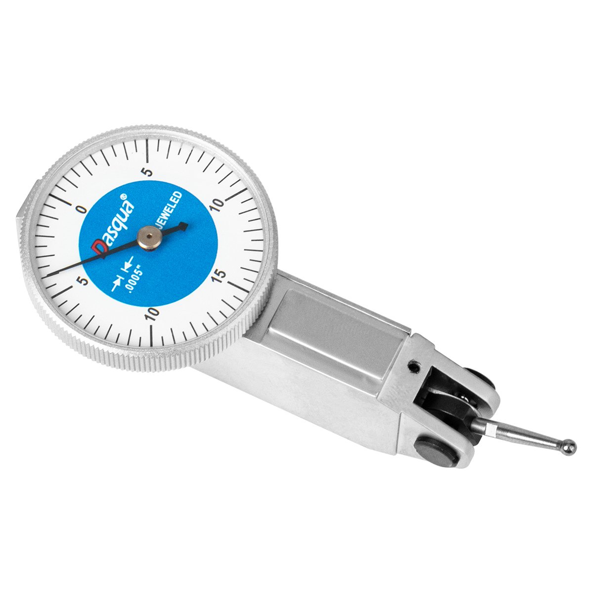
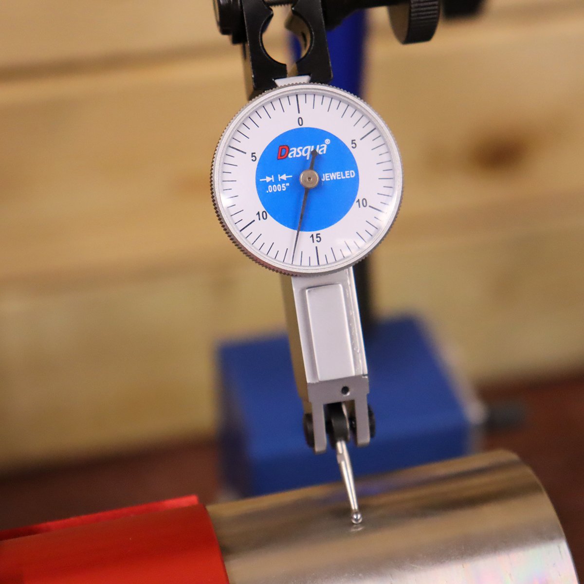
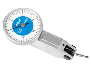
The Dasqua 5610-0165 compact dial test indicator combines a 0.03″ measuring range, fine 0.0005″ graduations and a balanced 0-15-0 dial in a slim 1.18″ face.
Its low-profile body and 0.62″ stylus provide access in setups where a larger indicator face or conventional plunger-style indicator may interfere with the spindle, chuck, fixture or machine enclosure.
Use it for comparative measurements, CNC vise alignment, spindle and chuck runout checks, bore centering, rotary-axis setup and other machine-tool inspection operations where small deviations need to be seen clearly.
Why Choose the Compact 1.18″ Face?
A large dial can be easier to read from a distance, but it may create clearance problems around small fixtures, internal bores and closely positioned machine components.
The 1.18″ / 30mm face makes this indicator a practical choice when:
- The indicator must fit between the spindle and workpiece
- A short holder position is required to reduce overhang
- The setup is inside a compact CNC enclosure
- A larger face could contact the vise, chuck or fixture
- The stylus must reach a narrow shoulder or internal surface
- The operator needs a lightweight indicator on a small holder
0.0005″ Graduations for Small Deviation Readings
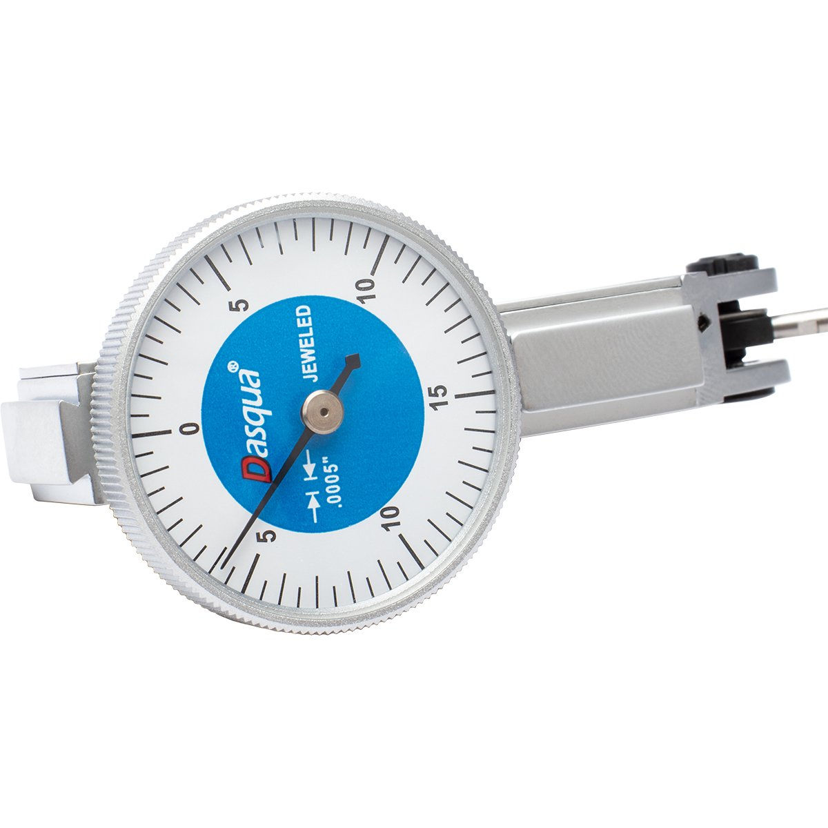
Each dial graduation represents 0.0005″, allowing the operator to observe small changes while aligning, centering or comparing machine surfaces.
The total measuring range is 0.03″. This makes the indicator suitable for fine comparative work rather than large linear displacement measurement.
For reliable readings, use the stylus at the correct contact angle and minimize cosine error. The indicator should be securely mounted so that holder movement is not mistaken for part or machine deviation.
Balanced 0-15-0 Dial for Alignment Work
The balanced 0-15-0 face places zero at the reference position and displays deviation on either side. This is useful when the objective is to adjust a component until movement is centered around zero.
Typical examples include:
- Aligning a milling vise with machine travel
- Centering a bore under a spindle
- Indicating a round part in a lathe chuck
- Checking whether a rotary fixture is centered
- Comparing two surfaces relative to a reference
This is a comparative indicator. It is intended primarily to show deviation from a reference rather than replace a micrometer or caliper for direct dimensional measurement.
Auto-Reversing Contact Movement
The auto-reversing contact mechanism allows the stylus to respond from either measuring direction while maintaining consistent clockwise hand movement.
This reduces visual confusion when switching contact direction during setup and makes it easier to interpret whether the reading is moving away from or back toward the selected reference.
Jeweled, Gear-Driven Mechanism
The precision gear-driven movement uses jeweled bearing points to support smooth response and reduce friction in the measuring mechanism.
A smooth mechanical response is important when sweeping a surface because the operator must distinguish actual workpiece deviation from hesitation or irregular movement inside the indicator.
All test indicators should be handled as precision instruments. Avoid impacts, excessive stylus travel and rapid uncontrolled contact with rotating or moving components.
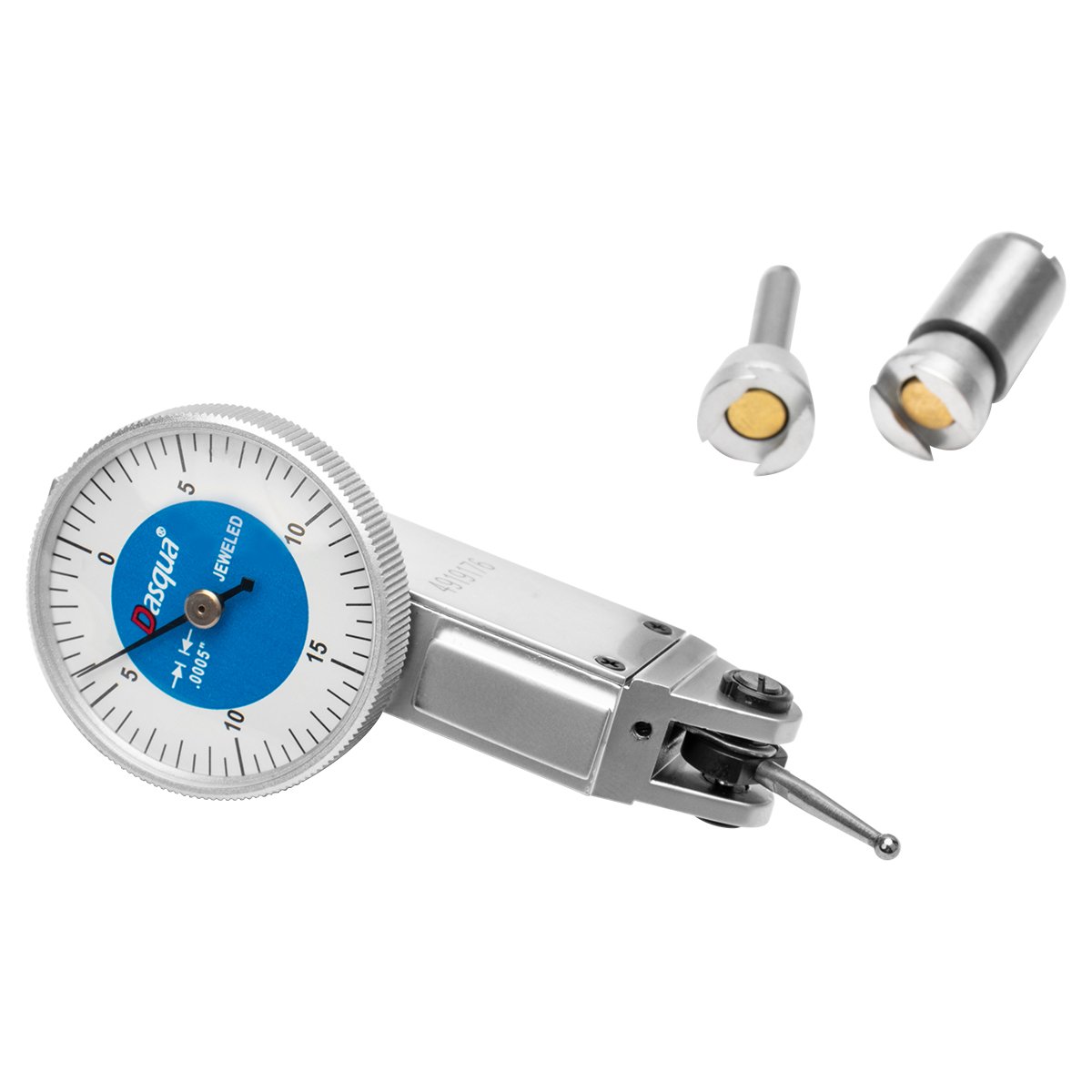
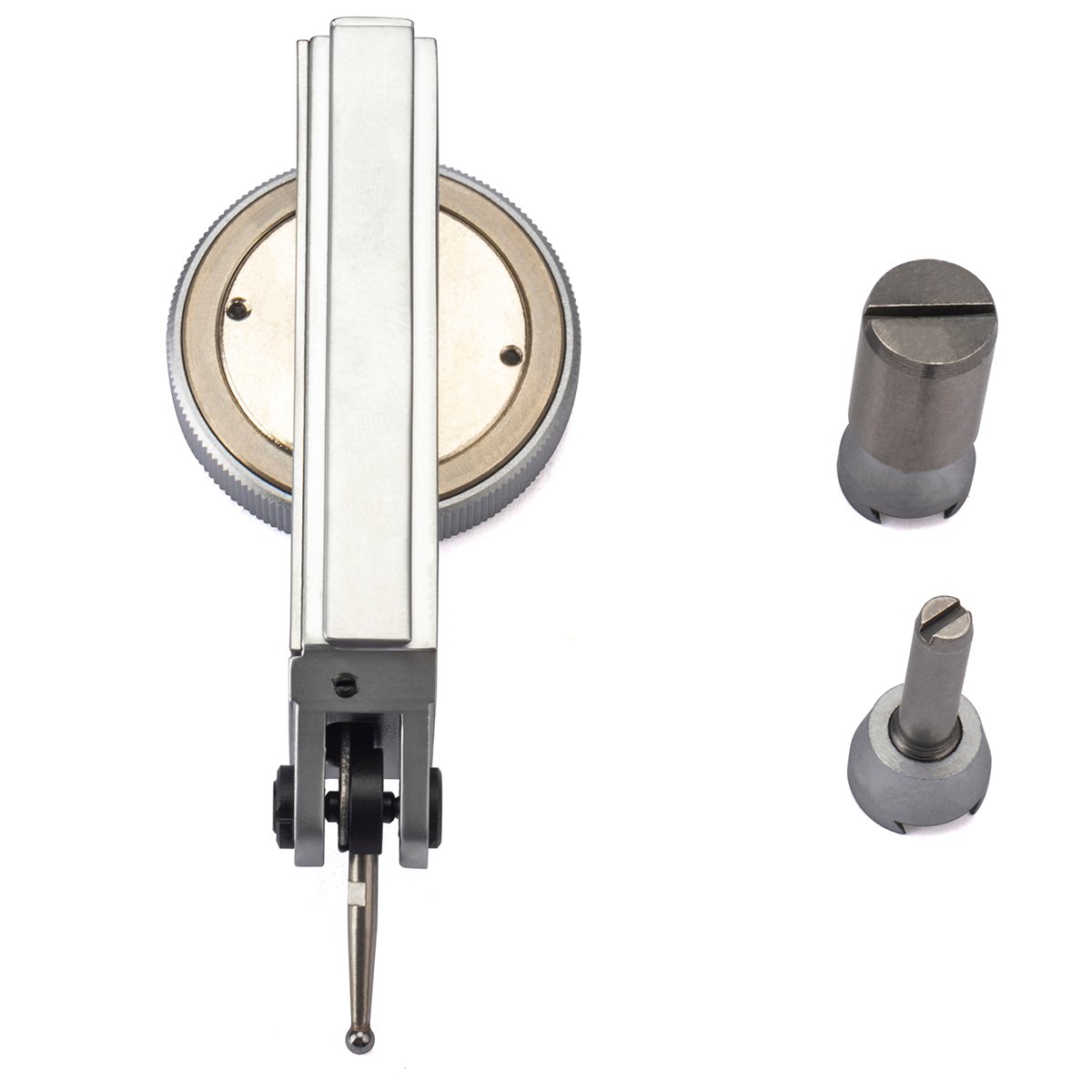
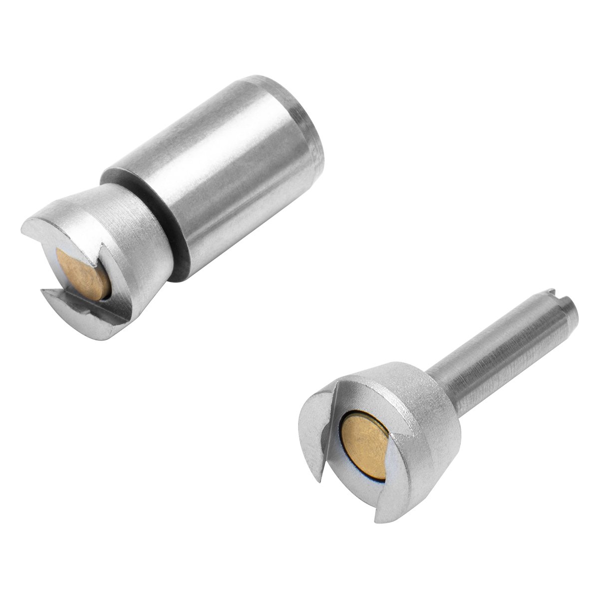
Two Dovetail Stems Included
The indicator includes two interchangeable dovetail mounting stems:
- 5/32″ stem
- 3/8″ stem
The dual-stem configuration expands compatibility with common test-indicator holders, articulated arms, magnetic bases and machine-mounted inspection accessories.
Verify the clamp size and dovetail orientation of the intended holder before ordering. A magnetic base or articulated holder is not specified as included with this individual indicator.
Clear White Face with Blue Insert
The high-contrast white dial and blue insert make the graduations easier to distinguish under typical shop lighting. A clear display helps reduce reading errors when the indicator is positioned inside a machine or viewed from an angle.
For the best reading, position the dial as close as practical to the operator’s direct line of sight and avoid relying on an extreme viewing angle.
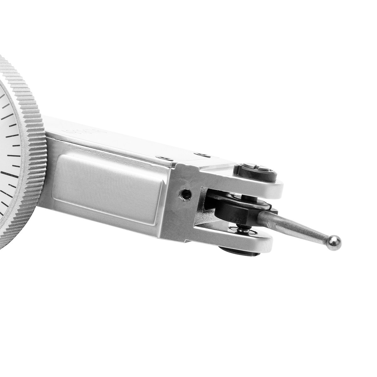
Friction-Adjustable 0.62″ Stylus
The 0.62″ stylus can be friction-adjusted to reach the required surface while maintaining a compact indicator body position.
The stylus angle affects measurement accuracy. Position it as close as practical to the manufacturer’s recommended measuring angle to reduce cosine error.
Do not use the stylus as a lever or apply force beyond its intended travel.
Hardened and Ground Contact Point
The contact point is hardened and ground to provide a durable measuring surface for routine machine-shop inspection.
The specified replacement is:
- Contact diameter: 0.080″
- Thread: M1.6
- Replacement reference: 5222-6004
Changing the stylus or contact point can affect effective length, contact geometry and measurement behavior. Use the correct replacement specification.
Applications on CNC Milling Machines
This compact indicator can support setup and verification tasks such as:
- Aligning vise jaws with the X-axis
- Checking fixture parallelism
- Centering a bore or circular feature
- Locating a rotary-table center
- Checking fixture and tombstone alignment
- Comparing workpiece heights or surfaces
- Verifying movement after clamping
Checking a CNC Vise
A vise that is not aligned with machine travel can introduce angular error across every part mounted against its fixed jaw.
To check alignment, mount the indicator securely, contact the vise reference surface and move the machine along the intended axis. Observe the total dial change and adjust the vise according to the required setup tolerance.
The 0-15-0 balanced face makes it easy to see whether the vise is moving toward or away from the zero reference during adjustment.
Lathe Chuck and Workpiece Runout
On a CNC or manual lathe, the indicator can be used to observe radial or axial variation on a compatible reference surface.
Possible applications include:
- Indicating a component in a 4-jaw chuck
- Checking workpiece runout after rechucking
- Comparing chuck-face movement
- Checking a test bar or arbor
- Verifying soft-jaw setup results
- Inspecting axial face variation
Stop or manually rotate the spindle according to safe shop procedures. Do not place hands, holders or indicators near a powered rotating chuck.
Bore Centering and Jig-Boring Setups
The lever-style contact is useful when sweeping the inside of a bore. As the spindle or holder is rotated manually, the indicator displays movement relative to the bore center.
This allows the operator to adjust the machine coordinates or workpiece position until the indicated variation is reduced to the required setup value.
Rotary Table and Fourth-Axis Alignment
The indicator can help verify the location and alignment of manual rotary tables, indexers and compatible CNC rotary axes.
- Sweeping a center bore
- Checking a fixture plate
- Aligning a tailstock with a rotary axis
- Comparing axial face movement
- Checking workpiece location before indexed machining
The indicator itself does not define the acceptable tolerance. Use the machine, fixture and workpiece specifications to establish the required alignment value.
Grinding and Toolroom Inspection
The compact body can also be useful in grinding and toolroom environments for comparative inspection of:
- Magnetic chuck alignment
- Fixture flatness and parallelism
- Toolmaker vise alignment
- Arbor and mandrel runout
- Gauge and inspection fixture movement
- Small precision components
Satin Chrome Body for Shop Use
The satin chrome finish helps resist routine wear and corrosion while reducing glare compared with a highly polished body.
Store the indicator clean and dry. Coolant, abrasive dust and chips should be removed carefully without forcing contamination into the movement.
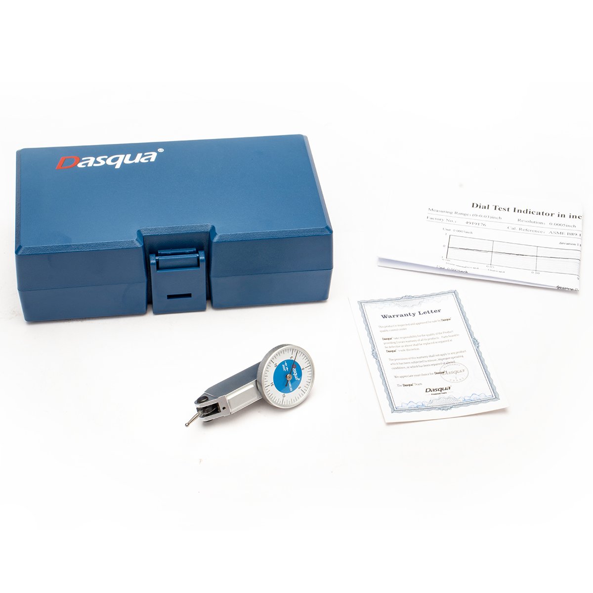
Factory Inspection Certificate Included
The indicator includes a factory inspection certificate documenting its inspection before shipment.
A factory certificate should not automatically be interpreted as an accredited third-party calibration certificate. If the application requires ISO/IEC 17025 traceability or a specific calibration interval, arrange the appropriate calibration service according to the company’s quality system.
ANSI/ASME Accuracy Statement
The supplied product information states that the indicator meets or exceeds applicable ANSI/ASME accuracy requirements. The exact standard designation is not identified in the supplied documentation.
For controlled inspection processes, confirm the required standard, calibration status and allowable uncertainty with the quality department before placing the instrument into service.
What Is Included?
- Dasqua compact dial test indicator
- Fitted protective storage case
- Foam case insert
- 5/32″ dovetail mounting stem
- 3/8″ dovetail mounting stem
- Factory inspection certificate
A magnetic base, articulating arm and separate indicator holder are not specified as included.
Technical Specifications
| Brand | Dasqua |
|---|---|
| SKU | 5610-0165 |
| Instrument Type | Lever-style dial test indicator |
| Measuring Range | 0.03″ |
| Graduation | 0.0005″ |
| Dial Configuration | Balanced 0-15-0 |
| Dial-Face Diameter | 1.18″ / approximately 30mm |
| Dial Color | White face with blue insert |
| Stylus Length | 0.62″ |
| Contact Movement | Auto-reversing |
| Movement Type | Jeweled, precision gear driven |
| Stylus Adjustment | Friction adjustable |
| Contact Point | Hardened and ground |
| Replacement Contact | 0.080″, M1.6 thread, reference 5222-6004 |
| Mounting Stems | 5/32″ and 3/8″ dovetail stems |
| Body Finish | Satin chrome |
| Certificate | Factory inspection certificate included |
| Storage | Fitted protective case included |
| Shipping Weight | 0.6 lbs |
Dial Test Indicator or Plunger Dial Indicator?
| Dial Test Indicator | Plunger Dial Indicator |
|---|---|
| Lever contact moves across the surface | Plunger moves along its own axis |
| Useful for alignment and runout checks | Useful for larger linear displacement |
| Compact access around bores and fixtures | Typically requires more direct axial clearance |
| Sensitive to stylus contact angle | Sensitive to plunger alignment |
Is This the Right Dasqua Indicator?
Choose the 5610-0165 when you need:
- A compact 1.18″ dial for restricted spaces
- 0.0005″ graduations
- A balanced 0-15-0 face
- 0.03″ comparative measuring range
- Dual dovetail mounting stems
- A standalone indicator with protective case
Choose another configuration if you need:
- A larger face for easier viewing from a distance
- A magnetic base and holder included
- Long-range plunger movement
- Digital output or direct numerical measurement
- An accredited calibration certificate supplied with purchase
Frequently Asked Questions
Is this indicator suitable for aligning a milling vise?
Yes. Its 0.0005″ graduations and balanced dial make it suitable for observing deviation while aligning a vise with machine travel.
Can it check lathe chuck runout?
Yes. It can be used for comparative radial or axial runout checks when mounted securely and used according to safe machine procedures.
Does it include a magnetic base?
No. This listing is for the indicator, protective case, two dovetail stems and factory inspection certificate.
What is the advantage of the 1.18″ face?
The compact face fits more easily between spindles, fixtures, chucks and workpieces where a larger indicator body may interfere.
What does 0-15-0 mean?
It identifies a balanced dial with zero at the reference position and graduations extending in both directions. This simplifies comparative alignment around a selected zero.
Is the inspection certificate an accredited calibration certificate?
Not necessarily. It documents factory inspection. Applications requiring accredited traceability should use an appropriate calibration provider.
Can the contact point be replaced?
Yes. The specified replacement has a 0.080″ contact and M1.6 thread. The listed reference is 5222-6004.
Choose the Best Dasqua Setup for Your Shop
| Need | Recommended Option |
|---|---|
| Compact standalone indicator | Dasqua 5610-0165 — current product |
| Larger dial for easier viewing | Dasqua 5610-0162 Large-Face Test Indicator |
| Complete inspection setup | Dasqua Magnetic Base and Indicator Kit |
| More indicator options | Browse Dial Test Indicators |
Compact Enough for Tight Setups—Sensitive Enough for Real Alignment Work
The Dasqua 5610-0165 gives machinists a compact mechanical indicator for the alignment and runout checks performed every day around CNC machines, mills, lathes, grinders and inspection fixtures.
Need the indicator only? Add the 5610-0165 to your quote. Need a complete ready-to-mount setup? Choose the linked Dasqua magnetic-base inspection kit or contact SHOP TOOL USA for help selecting a compatible holder.

Reviews
There are no reviews yet.