Technical Data Sheet: SNMG Carbide Insert (Grade SP8025)
The SNMG insert in grade SP8025 is a high-performance turning solution engineered for versatility and reliability in steel machining. Utilizing an advanced CVD (Chemical Vapor Deposition) multi-layer coating, this grade excels in balancing heat resistance with edge toughness.
Technical Specifications
| Feature | Description |
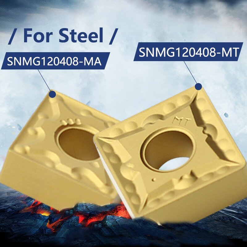
| ISO Range | P10 – P30 (Primary application: Steel) |
| Substrate | High-tenacity Carbide with superior anti-deformation resistance. |
| Coating Type | CVD Multi-Layer (MT-TiCN+Al2O3+TiN) |
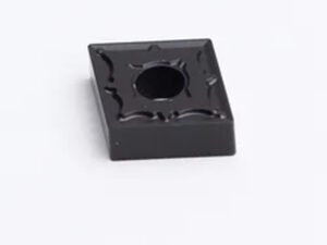
| Color | Golden Yellow (Top TiN layer for easy wear detection) |
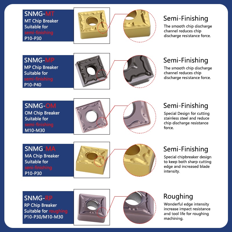
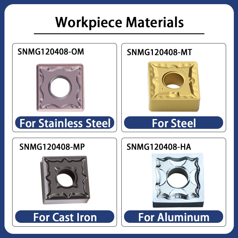
| Geometry | SNMG (Square, Double-sided, 90° Negative) |
Key Features Grade Carbide SP8025
Advanced Coating Stack: * MT-TiCN: Provides hard wear resistance against abrasive forces.
Al2O3 (Alumina): Acts as a thermal barrier, protecting the substrate during high-speed dry machining or high-heat conditions.
TiN (Titanium Nitride): The golden top layer not only reduces friction but serves as a “wear indicator”—making it easy to see which edges have been used.
Substrate Integrity: The carbide base is formulated to resist “plastic deformation,” ensuring the tool maintains its shape even under the heavy pressures of roughing.
Usage Recommendations
1. Primary Applications
Materials: Ideal for carbon steels, alloy steels, and tool steels.
Operations: Optimized for Semi-Finishing to Roughing.
Cutting Conditions: Excellent for general-purpose machining, including continuous cuts and light interrupted cuts.
2. Practical Tips for SP8025
Speed & Feed: Because of the Al2O3 layer, you can push higher cutting speeds than standard uncoated or PVD grades without immediate thermal failure.
Wear Monitoring: Take advantage of the golden yellow finish. If the gold layer is rubbed off to reveal the darker layers underneath, it’s time to inspect the edge for flank wear.
Stability: Ensure a rigid setup. While the substrate is tough, SNMG inserts are negative geometry and require adequate machine horsepower and stability to prevent vibration during heavy roughing.
Note: For heavy intermittent cuts (impact loading), ensure your feed rates are adjusted to prevent micro-chipping, despite the substrate’s high toughness.
| Material Type | Hardness (HB) | Cutting Speed (Vc) | Feed Rate (f) |
| Low Carbon Steel (1018, A36) | 125 – 175 | 250 – 350 m/min | 0.20 – 0.50 mm/rev |
| Alloy Steel (4140, 4340, 8620) | 200 – 275 | 180 – 280 m/min | 0.15 – 0.45 mm/rev |
| Tool Steel (D2, H13, P20) | 180 – 250 | 120 – 200 m/min | 0.15 – 0.40 mm/rev |
| Cast Steel | 200 – 250 | 150 – 230 m/min | 0.20 – 0.45 mm/rev |
Optimization Pro-Tips for SP8025
Chip Control: If you are “bird-nesting” (long, stringy chips), increase your Feed Rate (f). The SNMG geometry relies on the chip breaker to snap the material; it needs enough pressure to work.
Depth of Cut (ap): For roughing with an SNMG insert, your depth of cut should typically be between 1.0mm and 5.0mm, depending on your machine’s rigidity and the insert’s nose radius.
Dry vs. Wet: While the Al2O3 layer allows for dry machining, using high-pressure coolant will significantly extend tool life in stainless or gummy low-carbon steels.